Automatic Plant Watering System with Arduino
Why ?
I wanted to build a system capable of watering my plants with minimal maintenance.
The system must meet these requirements:
- Instant start/stop
- Safe in case of problem (no flooding, failure detection)
- State displayed
- Programmable (timer on/off) to avoid night disturbances
- Autonomous detection of moisture levels and watering trigger
- Control each pump state
Materials used
To meet each requirements for this system, and keep the price low, I used these materials (each number correspond to the requirements numbers):
- Arduino UNO for instant start, and a big red kill switch to cut electricity quickly.
- The program detects anomalies and blocks pumps from watering
- I2C 128x64 OLED Screen
- Push button to loop through various system states.
- Program interacting with:
- 2x Soil humidity sensors for detection
- 2x 12V Water Pumps
- 2x 12V Relay to power the pumps
- ON/OFF Switches
And many wires, and Heat Shrink Tubes, with a breadboard.
Software explanation
Each pump has a status:
- READY: The pump is enabled and waiting for all the good conditions before running. The event preventing the pump from running is displayed in the “wait” column.
- RUN: If there is no event in “wait” column, the pump is actively watering the plant until the running timer is finished. → Will switch to PAUSED
- PAUSED: The pump is disabled after running, waiting for a timer to end before going back to READY state. This ensures there is a delay between 2 activation to let the water soak evenly in the soil and reach the sensor. The timer is written in the “wait” column for the pump.
- LVL_ERR: The reading from the sensor is abnormal (under 10% or over 90% of humidity). The pump is not allowed to run until the readings goes back to normal.
- BLOCKED: There is an anomaly detected, either the pump does not works (e.g. electrical problem, no more water in water tank…), or the sensor is broken. This state is triggered automatically when the moisure level hasn’t gone up of at least 2% after 3 successive triggers. For safety, the only way to unblock a pump is by going in manual mode and checking the blocked pump.
- OFF: The switch for the pump is set to OFF position. The pump is disabled.
The “wait” events can be: A timer, a pump status (wait pump to be ON), a refresh of the sensor reading, a system status (wait system to be ON), a moisture level.
This is the state machine diagram for each pump:
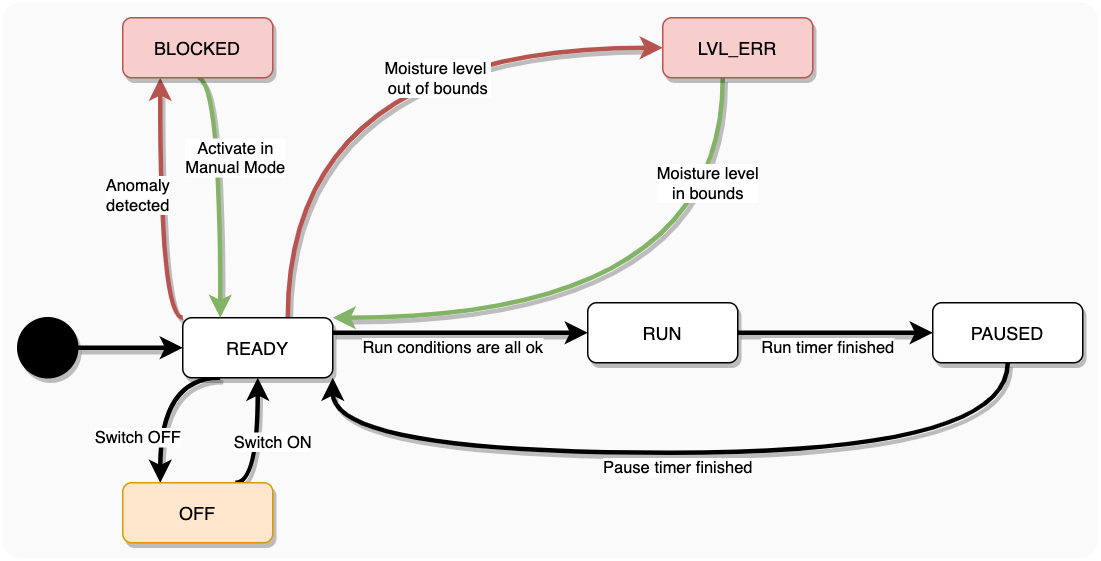
Pump state machine diagram.
There are multiple states for the system:
- System is ON
- Timer is ON (→ Will switch to System OFF, Timer ON)
- Timer is OFF
- System is OFF
- Timer is ON (→ Will switch to System ON, Timer ON)
- Timer is OFF
- Manual Mode
In modes 1 and 2, the two switches are used to enable or disable each pump (enabled means setting the pump’s state to READY).
In Manual Mode, the switches actually trigger the pumps, they will run until the switch is turned off (pump status RUNNING).
Looping through modes is done with the state control button, to enter the Manual Mode, all pumps switches must be turned OFF.
This is the corresponding State Machine diagram for System States:
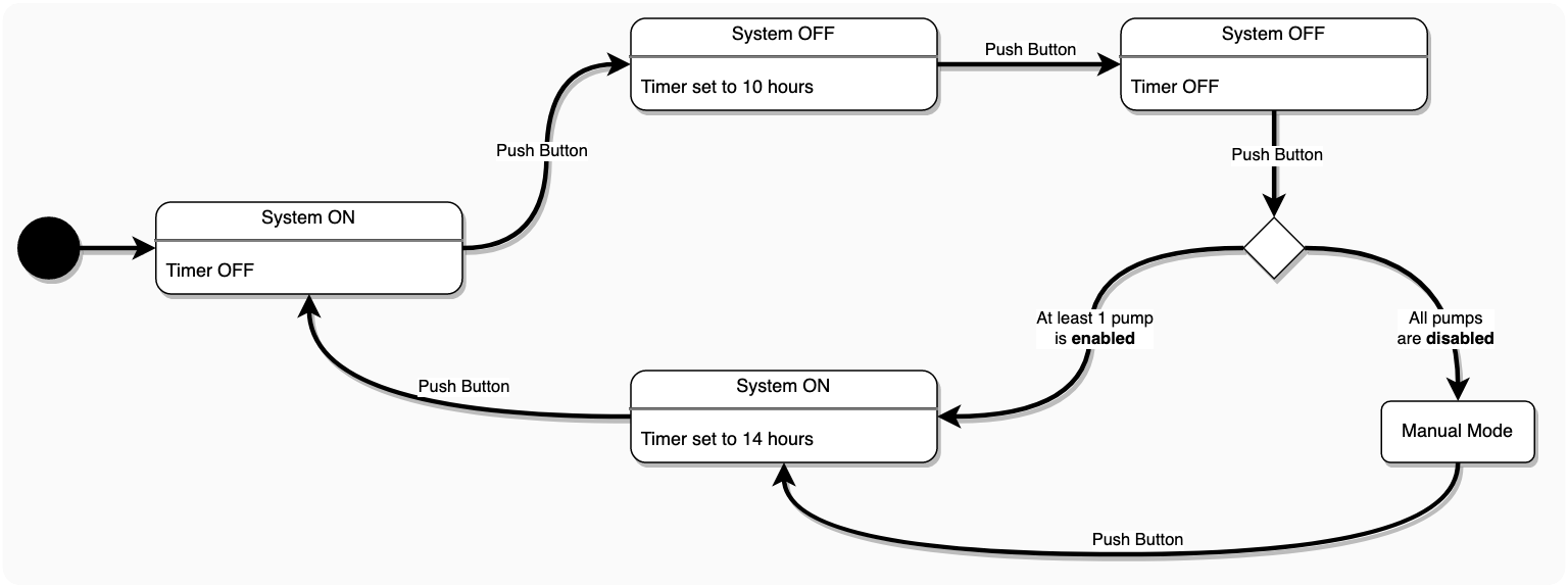
System state machine diagram.
Wiring everything
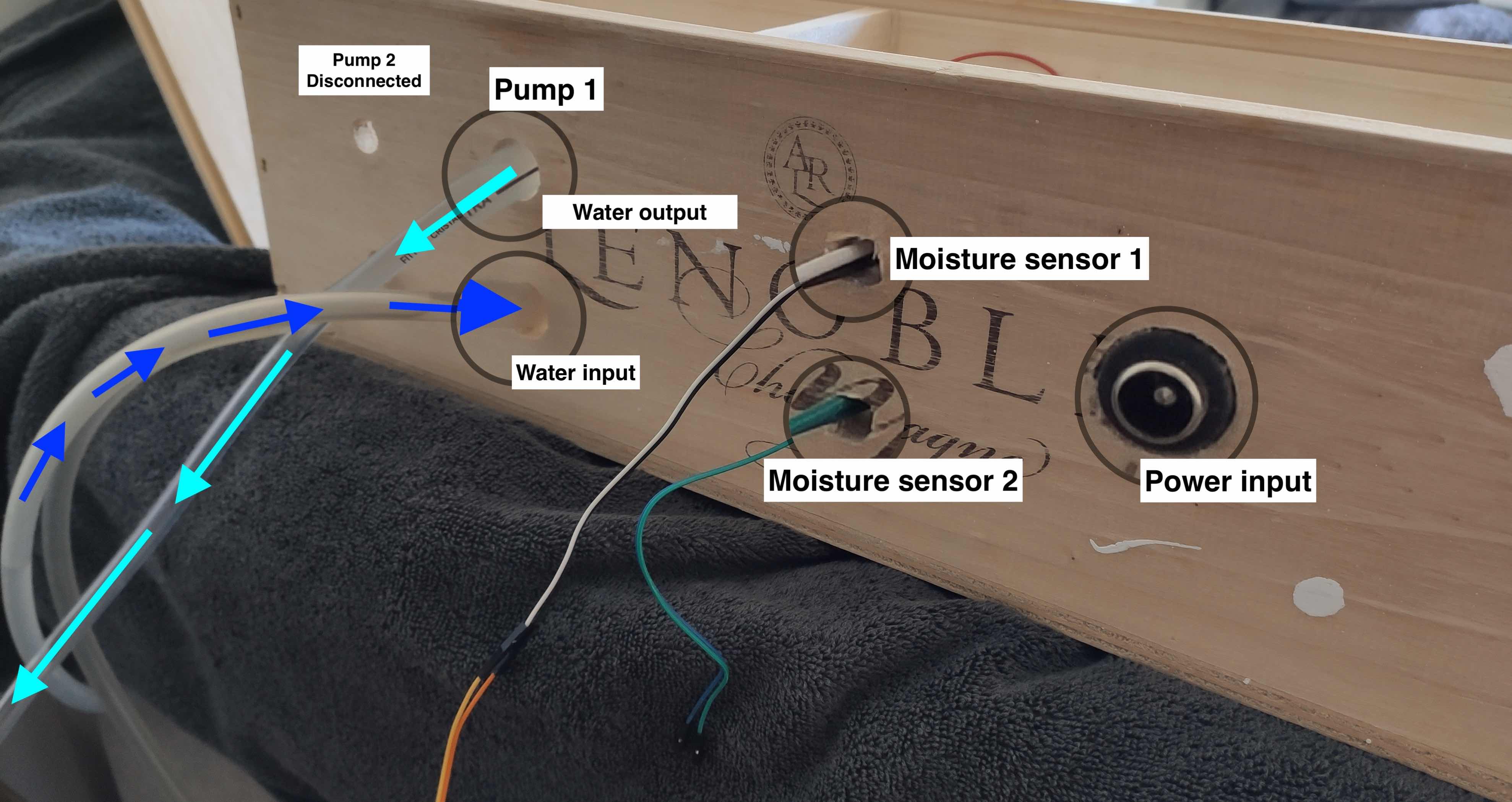
To be as clear as possible, here is the wiring I have done:
Wiring with all components.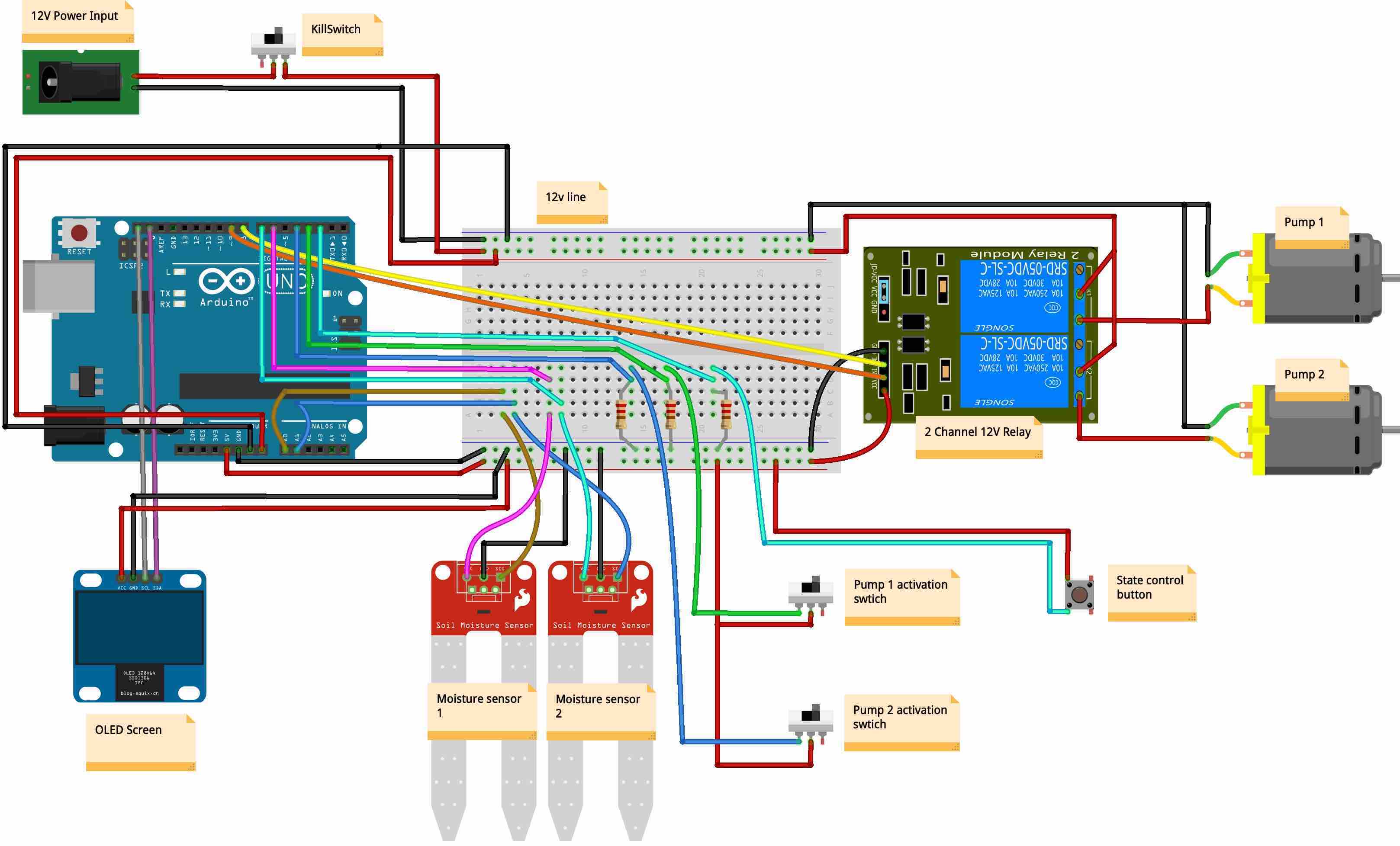
Views of final product
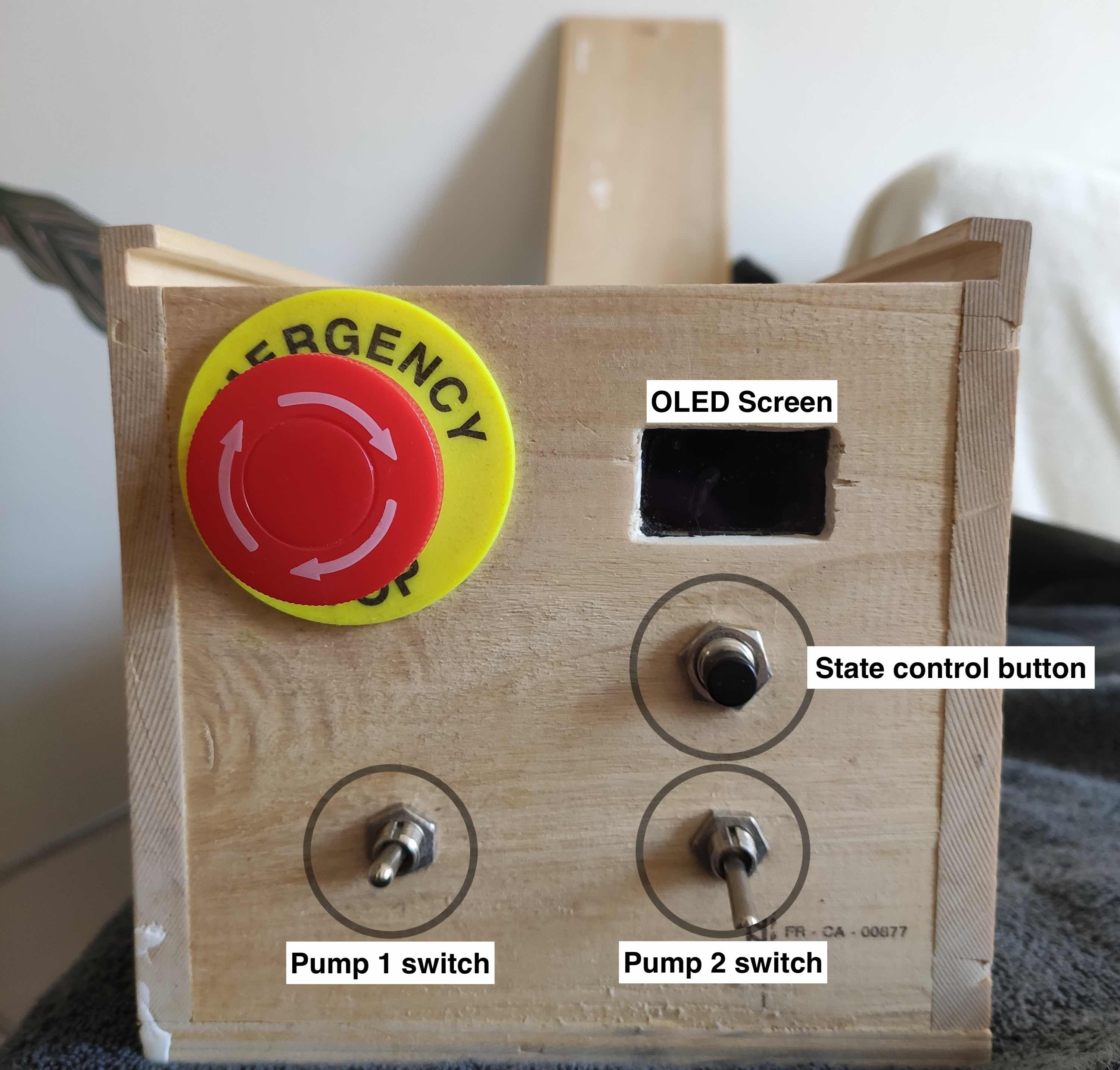
The top view, facing the roof in usual conditions.
Side view.
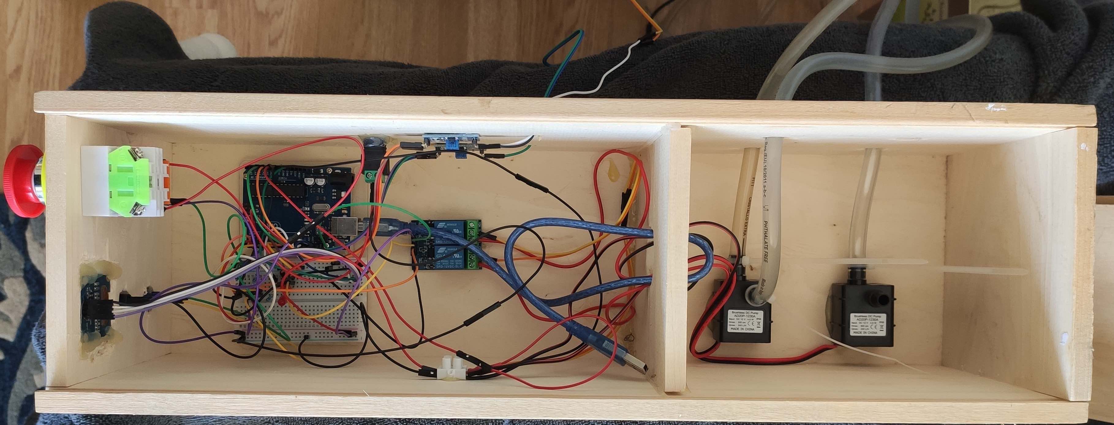
Inside view. Electrical circuit and water circuit are separated, the pumps are at the bottom to avoid any damage in case of leak.
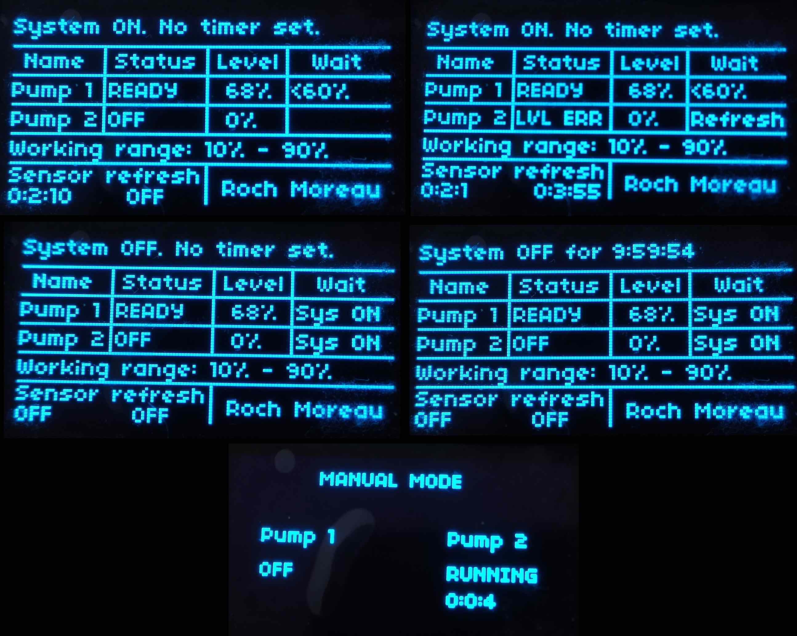
Some display views with various system states and pump status.
Coding part
The code is hosted on github, available here.
It is divided in 3 parts:
line 1 to 53Variable declaration, holding the configuration and the state of the systemline 54 to 302The display control part: displays the right view based on the state of the machine (System/timer on/off or test mode), and the status of each component (moisture level, pump threshold, pump state)line 304 to 477System control part.
Enhancements
After completing this project, I have some thoughts and ideas on how to enhance it and what I would like to change.
For the aesthetic, I used a box of champagne that was laying around. A 3D printed box could have been a better choice.
About the code, everything is in the same file. Object-Oriented Programming could be a better fit, one class for the display, one pump class, one sensor class.
I used brushless motor pumps. They works well as long as there is water under pressure in input pipe: the water tank must be above the pump. Vacuum Pump are more pricy but works even if the water tank is lower than the pumps.
The moisture threshold is hardcoded for each sensor, meaning if you change the plant, you must change the code to match the plant’s moisture needs, and update the arduino (this is why the Debugging USB Cable is still in the champagne box 🧙♂️). I see two ways for solving this:
- Create a new state “Settings” and use a potentiometer to vary the hardcoded values
- Go IoT mode 🚀 A quick way is setting up MQTT to send and receive data
Pro Tips 🌱
I have a Calathea, and she really seems to enjoy 60% moisture. It’s been 7 months and she hasn’t stopped growing!
Edit:
A big thank to Pierre Fontaine, who suggested adding state-machine diagrams and some improvements on this article !